The best high bay lighting for a factory depends on ceiling height and floor layout. UFO LED high bays deliver concentrated downward light for open production floors with 20 to 40 ft ceilings. Linear LED high bays provide continuous, uniform illumination over assembly lines and conveyor belts. Match beam angle to aisle width, and mount fixtures to avoid shadows from overhead cranes and ductwork.
Dave runs a stamping plant in Ohio with a 30-ft ceiling, an overhead crane that spans the full width of the floor, and a conveyor belt that feeds blanks into three progressive dies. When his maintenance crew relamped the metal halide high bays last year, they hung the new fixtures in the same locations as the old ones.
Within a week, operators complained that the crane cast a moving shadow across the die-change area. The conveyor belt operators reported glare when they looked up to clear jams. Dave realized that warehouse spacing logic doesn’t work when you’ve got moving equipment and continuous production lines.
This guide solves that problem. You’ll get a zone-by-zone fixture selection framework, production-line spacing methodology, and mounting guidance that respects real factory constraints like cranes, ductwork, and conveyors.
For the broader strategic framework on factory lighting design, see our complete guide to (factory lighting solutions).
Key Takeaways
- UFO high bays suit open production floors and high ceilings; linear high bays suit assembly lines and conveyor belts where continuous light matters.
- Factory spacing ratios (1.0 to 1.5 x mounting height) differ from warehouse aisle spacing because production lines need uniform task illumination, not just aisle coverage.
- Overhead cranes require 3 to 5 ft fixture clearance; offset mounting or dual rows eliminate crane-shadow dead zones.
- UGR (Unified Glare Rating) thresholds differ by task: UGR <19 for precision assembly, UGR <22 for general production.
- A photometric study is worth the cost for new construction or precision tasks; simple one-for-one retrofits can use rules of thumb.
UFO vs. Linear High Bay: Which One Belongs Over Your Production Line?

Most high bay guides treat UFO and linear as interchangeable. In a factory, they aren’t. The right choice depends on what happens under the light.
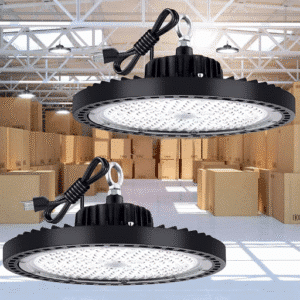
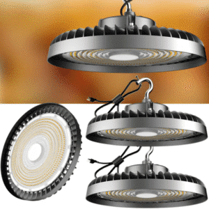
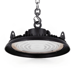
UFO LED High Bay: Concentrated Beams for Open Floors
UFO fixtures are round, compact, and designed to project a concentrated cone of light downward. They excel in open production floors where the goal is broad, uniform ambient illumination without a specific linear task pattern.
Best applications for UFO high bays in factories:
- Open production floors with 20 to 40 ft ceilings
- Areas without continuous assembly lines
- CNC machining cells where concentrated light on a single workstation is the priority
- Raw material storage and staging zones within the factory
Beam angle selection matters. A 60° beam concentrates light in a narrow circle, ideal for high ceilings or focused workstations. A 90° beam covers a moderate area, the most common choice for 25 to 35 ft ceilings. A 120° beam spreads light widely, useful for lower ceilings or open floors where maximum coverage per fixture is the goal.
Linear LED High Bay: Continuous Uniform Light for Lines
Linear fixtures are rectangular and designed to distribute light along a length, not just downward in a circle. They excel wherever people work along a continuous path.
Best applications for linear high bays in factories:
- Assembly lines and conveyor belts
- Long workbenches and inspection stations
- Racking and shelving rows within factory boundaries
- Packaging and shipping lines
The key advantage is uniformity. A point-source UFO creates a bright spot directly below the fixture that fades toward the edges. A linear fixture, when mounted end-to-end or in closely spaced rows, delivers consistent foot-candles along the entire length of a production line. That matters when an assembler at station 47 needs the same visibility as an assembler at station 3.
For a full shape comparison, see our (UFO vs. linear high bay analysis).
The Decision Matrix: 5 Factory Zones and the Right Fixture
| Factory Zone | Recommended Fixture | Beam Angle / Layout | Why |
|---|---|---|---|
| Open production floor | UFO LED high bay | 90° to 120° | Broad ambient coverage, no continuous line |
| Assembly line | Linear LED high bay | Continuous or end-to-end | Uniform task light along the line |
| Conveyor belt | Linear or UFO narrow beam | Linear continuous, or UFO 60° | Depends on belt width and surrounding activity |
| CNC / machining cell | UFO LED high bay | 60° to 90° | Concentrated light on workstation, high CRI |
| Raw material storage | UFO LED high bay | 120° | Wide coverage for pallet staging areas |
For zone-by-zone specification guidance, see our (best lighting for manufacturing plants buyer’s guide).
Spacing High Bay Fixtures Over Production Lines

The Spacing Ratio Method for Production Floors
The standard formula for high bay spacing is simple: Spacing = Mounting Height x Spacing Ratio. In factories, the spacing ratio typically falls between 1.0 and 1.5, depending on the uniformity you need.
Warehouse spacing often uses tighter ratios (0.8 to 1.0) because the goal is aisle coverage between racking. Factory spacing needs looser ratios because the goal is task illumination across open work areas where machinery and workstations are distributed more randomly.
Worked example: 30-ft ceiling, 90° UFO, 1.2 spacing ratio.
30 ft x 1.2 = 36 ft on center. For a 200 ft x 100 ft production floor, that translates to roughly 6 rows of 5 fixtures, or 30 total.
Continuous Line Spacing for Linear High Bays
Linear fixtures use different logic. Instead of a spacing ratio, you think in terms of row spacing and fixture overlap.
For a continuous assembly line, mount linear fixtures in parallel rows above the line. Row spacing depends on mounting height: at 20 ft, 8 to 10 ft between rows works. At 30 ft, 10 to 12 ft between rows maintains uniformity.
Worked example: 20-ft ceiling, 8-ft linear fixtures, 10-ft row spacing over a 200-ft assembly line.
You would run two rows of 25 fixtures each (200 ft / 8 ft = 25 fixtures per row), for 50 total linear high bays.
Avoiding Shadows from Overhead Cranes and Ductwork
Overhead cranes are the single biggest constraint on factory lighting layout. OSHA 1910.179 requires minimum clearance between cranes and obstructions. Best practice is 3 to 5 ft between the crane envelope and any fixture.
When a fixture cannot be centered because of a crane rail or duct, use offset mounting. Mount fixtures slightly off-center of the work area, and compensate with a narrower beam angle or a second offset row on the opposite side.
Dual rows eliminate crane-shadow dead zones. If a single row of fixtures would cast a shadow when the crane passes, split the fixtures into two parallel rows flanking the crane path. The light from each row covers the shadow zone of the other.
Vertical Illumination for Shelving and Racking Within Factory
Horizontal foot-candles, measured at the work plane, are only half the story. In factories with shelving, vertical surfaces matter too. Labels, barcodes, and inventory tags on vertical racks need illumination.
Beam angle selection drives vertical illumination. A 120° beam spreads light widely, including onto vertical surfaces. A 60° beam concentrates light downward and may leave rack faces in shadow. For mixed-use factory floors with both work areas and storage racking, 90° to 120° beams are the safer choice.
Mounting High Bays in Real Factory Ceilings
Pendant Drop and Cable Suspension
Factory ceilings are rarely clean. Ductwork, sprinkler lines, and cable trays often occupy the space where you want to mount fixtures. The solution is pendant drop: suspending fixtures 3 to 6 ft below the ceiling on cables or rigid conduit.
Cable suspension is faster to install and allows some adjustment. Rigid conduit is more secure and meets seismic bracing requirements in earthquake zones. In California and other seismic regions, local codes may require rigid conduit with seismic bracing for fixtures over 20 lbs.
Mounting Around Overhead Cranes and Hoists
Crane hook height determines your maximum pendant length. The fixture must remain above the highest point the crane hook or load reaches, including the swing envelope. A typical stamping-plant crane with a 25-ft hook height and 3-ft load swing requires fixtures mounted at 29 ft or higher.
In low-clearance areas where fixtures are close to crane paths, specify IK10 impact-rated housings. A swinging load can destroy an unprotected fixture. IK10 is the highest impact rating in the IEC standard and withstands a 5-joule impact, equivalent to a 2-kg mass dropped from 250 mm.
Electrical Load and Circuit Planning
Group fixtures by zone for independent control. Production lines, storage areas, and shipping docks should be on separate circuits. This allows you to shut down non-production zones during off shifts without affecting active lines.
Voltage drop matters on long production lines. For a 200-ft assembly line with 25 fixtures per row, the farthest fixture may be 150 ft from the electrical panel. At 150W per fixture and 120V, voltage drop across 150 ft of 12-gauge wire is roughly 3 percent. For longer runs or higher wattages, step up to 10-gauge wire or add a sub-panel mid-line.
Glare Control and Operator Comfort
UGR Thresholds for Factory Tasks
UGR, or Unified Glare Rating, measures how much discomfort a light source causes to an observer. Lower numbers mean less glare. IES standards recommend:
- UGR <19: Precision assembly, inspection, and quality control stations
- UGR <22: General production, machining, and material handling
- UGR <25: Storage, shipping, and peripheral areas
Fixture optics affect UGR more than wattage. A lens with a diffused micro-prismatic surface scatters light and reduces glare compared to a bare reflector. If your operators complain about “bright spots” or squinting, the problem is usually optical, not output.
Anti-Glare for Conveyor Belt Operators
Conveyor belt operators are uniquely vulnerable to glare. They stand in a fixed position, look up frequently to clear jams, and cannot move away from the light source. Diffused lens options and louvers cut glare by 30 to 50 percent without reducing total lumen output.
Mounting angle also matters. Tilt linear fixtures 5 to 10 degrees away from the operator position so the light hits the belt, not the operator’s eyes.
Stroboscopic Effect and Flicker in Moving Machinery Zones
Low-quality LED drivers can produce flicker at frequencies that are invisible to the naked eye but create a stroboscopic effect near rotating equipment. A spinning shaft or flywheel may appear to move in slow motion or reverse direction under flickering light. This is a safety hazard.
Specify flicker-free drivers with less than 5 percent flicker at 120 Hz. Most reputable LED high bay manufacturers publish flicker percentage in their spec sheets.
Specs That Matter for Factory High Bays

Lumen Output and Efficacy by Ceiling Height
| Ceiling Height | Recommended Lumens | Typical Wattage (DLC Premium) |
|---|---|---|
| 20 to 25 ft | 15,000 to 20,000 lm | 100W to 150W |
| 25 to 35 ft | 20,000 to 30,000 lm | 150W to 200W |
| 35 to 45 ft | 30,000 to 40,000+ lm | 200W to 300W |
Efficacy, measured in lumens per watt, tells you how efficiently a fixture converts electricity into light. DLC Premium fixtures typically deliver 140 to 180 lm/W.
A 150W fixture at 160 lm/W produces 24,000 lumens. An older LED fixture at 120 lm/W would need 200W to match that output. Those efficacy differences directly affect your energy bill.
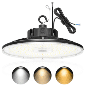
Color Temperature for Production Floors
4000K (neutral white) and 5000K (daylight white) are the standard choices for factory floors. 4000K is slightly warmer and reduces eye strain during long shifts. 5000K is cooler and provides sharper contrast for detail work.
Some facilities mix color temperatures: 5000K over inspection and assembly lines, 4000K in break rooms and shipping areas. This requires planning during specification because fixtures with different color temperatures shouldn’t be mixed in the same task zone.
CRI for Quality Inspection and Color-Matching Tasks
CRI (Color Rendering Index) measures how accurately a light source reveals the true colors of objects. For factory lighting:
- CRI 80+: Minimum for general production and material handling
- CRI 90+: Required for inspection, paint matching, electronics assembly, and any task where color accuracy affects quality
Linda runs an electronics assembly plant in Minnesota. After switching from CRI 80 to CRI 92 linear high bays over her inspection stations, her defect-detection rate improved 11 percent.
Operators could see solder joint quality and component alignment more clearly. For a deep dive on precision task lighting, see our (precision manufacturing lighting guide).
IP and IK Ratings for Factory Environments
Ingress protection and impact resistance ratings define how well a fixture survives factory conditions.
- IP65: Dust-tight and protected against water jets. Minimum for most factory floors.
- IP66: Dust-tight and protected against powerful water jets. Required for washdown areas and food processing.
- IP69K: Protected against close-range high-pressure, high-temperature washdowns. Used in food and pharmaceutical plants.
- IK08: Withstands 5-joule impact. Adequate for general factory use.
- IK10: Withstands 20-joule impact. Required near stamping presses, forging equipment, and crane zones.
Smart Controls for Factory High Bays
Motion Sensors in Intermittent-Use Production Zones
Motion sensors save energy in break rooms, shipping docks, restrooms, and storage areas where lighting does not need to run continuously. In production areas, sensors are rarely used because sudden shutoff creates a safety hazard when an operator is mid-task.
Dimming for Shift-Based Operations
Dimming is more practical than motion sensors for production floors. Dim non-critical zones to 50 percent during lunch breaks and changeovers. Dim entire floors to 30 percent during off-shift maintenance windows.
0-10V dimming is the simplest protocol and works with most industrial controls. DALI offers individual fixture addressing and feedback, useful for large facilities with complex zone control.
For manufacturing-specific control strategies, see our (smart factory lighting systems guide).
Factory Lighting Layout: When to Call in a Photometric Study

What a Photometric Study Delivers
A photometric study is a computer simulation that predicts how your chosen fixtures will perform in your actual space. It produces three deliverables:
- Predicted foot-candle map: A color-coded floor plan showing illumination levels at every point
- Uniformity ratio: The minimum foot-candle divided by the average foot-candle. A ratio above 0.6 is generally acceptable for factories.
- Shadow and glare analysis: Identification of dark zones and high-glare positions before you buy a single fixture
When You Need One vs. When Rules of Thumb Work
You need a photometric study when:
- You’re building a new facility or adding a new production line
- Precision tasks require uniform illumination (UGR <19, uniformity >0.7)
- You’re preparing for an OSHA compliance audit
- The ceiling has complex obstructions (cranes, mezzanines, equipment platforms)
Rules of thumb work when:
- You’re doing a one-for-one retrofit with the same mounting locations
- The space is a simple rectangle with no major obstructions
- Your goal is general illumination, not precision task lighting
Most photometric studies cost 500to500to2,000 depending on facility complexity. For a large new factory, that cost is negligible compared to the cost of installing the wrong fixtures and relamping.
For layout methodology guidance, see our (factory lighting layout design guide).
Conclusion
High bay lighting for a factory isn’t warehouse lighting with a different title. Production lines, conveyor belts, overhead cranes, and moving equipment create constraints that warehouse guides ignore. The right fixture for the right zone, spaced and mounted around real factory infrastructure, makes the difference between adequate light and optimized operations.
UFO high bays win on open floors and high ceilings. Linear high bays win on assembly lines and conveyor belts. Spacing by mounting height, not by guesswork.
Mounting that respects crane envelopes and ductwork. Glare control that keeps operators comfortable during long shifts. Those are the principles that separate a functional retrofit from one that improves safety, quality, and productivity.
The IES, DOE, and OSHA frameworks are your reference. Probapro is the engineering partner that translates them into fixtures mounted on your ceiling, verified by photometric data, and backed by industrial-grade warranties.
Ready to take the next step? Sketch your floor plan, note your ceiling height and crane locations, and send them over. With that information, Probapro can deliver a fixture recommendation, spacing layout, and photometric preview that is ready for your next maintenance budget meeting.